
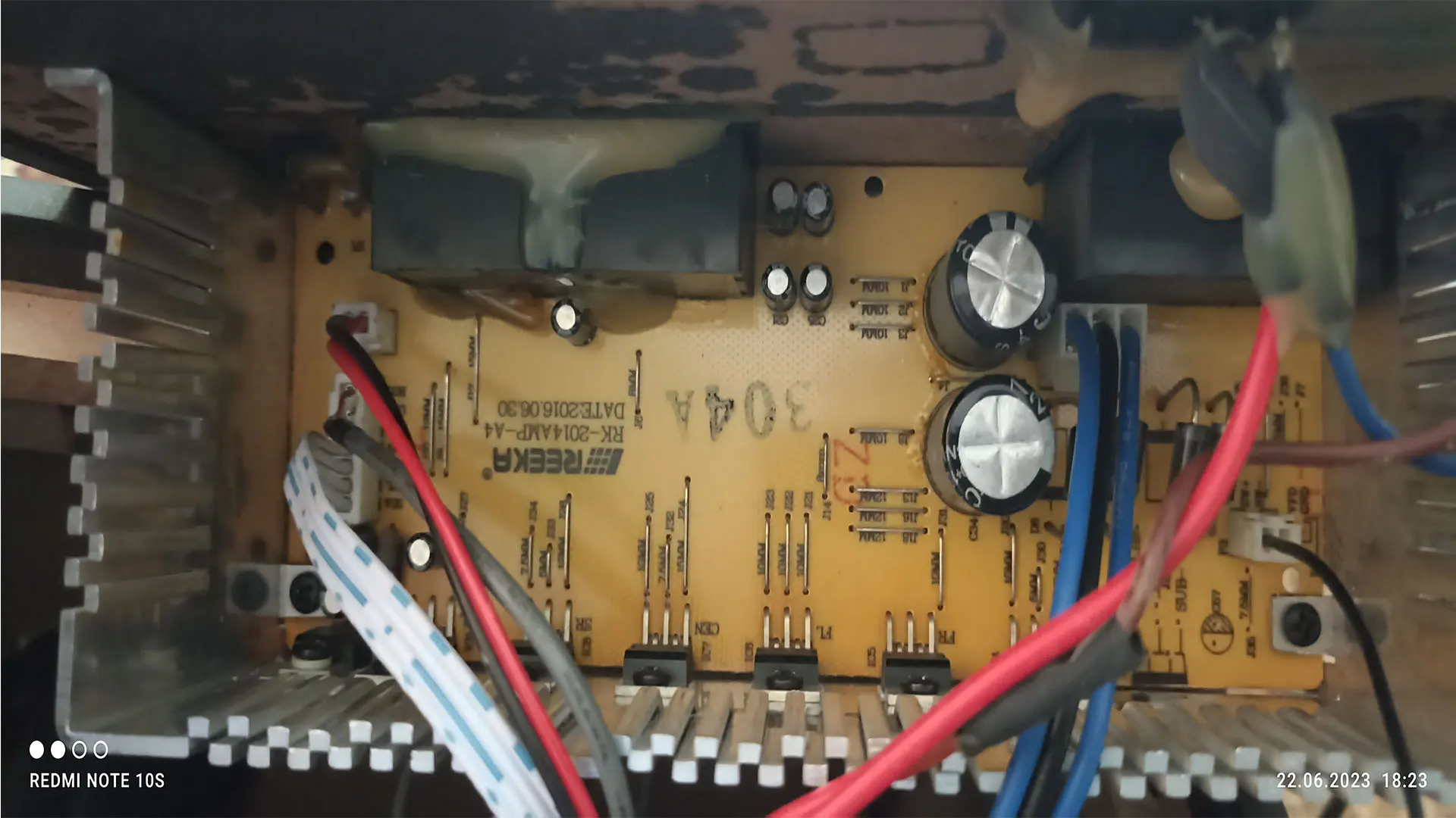
How a $2 Fix Saved My Akai SS030A-5518 Amplifier!
An audio power amplifier that boots up cleanly from a cold state but abruptly cuts off or triggers protection mode after 5 to 10 minutes of operation is presenting a classic thermal management failure. In this comprehensive technical guide, we disassemble and repair an Akai SS030A-5518 5.1-channel active home theater speaker system suffering from thermal protection shutdowns.
We will examine the underlying schematic architecture of AB-class power stages, analyze the physics of semiconductor thermal resistance (Rθ), inspect the NTC thermistor sensor protection loops, and outline the precise replacement procedure for degraded Thermal Interface Material (TIM) on the final stage output transistors.
1. Technical Specifications & Architecture Overview
The Akai SS030A-5518 is an integrated 5.1 surround sound audio system featuring a central subwoofer unit housing the main AC power transformer, primary rectifiers, signal filtering circuit, and multi-channel power amplifier board.
| Parameter | Technical Specification
|
|---|---|
| System Configuration | 5.1 Channel Active Subwoofer & Speaker System |
| Output Power (RMS) | Subwoofer: 30W (4Ω) | Satellites: 5 x 10W (4Ω) |
| Amplifier Topology | Class AB Push-Pull / Monolithic IC Output Stage |
| Frequency Response | 35 Hz – 20 kHz |
| Signal-to-Noise Ratio (SNR) | ≥ 70 dB |
| Operating Power Supply | AC 220V–240V / 50Hz (Internal Linear Transformer with Dual Secondary Winding) |
| Thermal Protection Mechanism | NTC Thermistor Sensor coupled to Output Stage Heatsink / Internal Die TSD |
2. Circuit Schematic & Block Diagram Analysis
The power stage relies on complementary push-pull topology (or multi-channel high-power ICs like TDA2030/TDA2050 series or Discrete Bipolar Junction Transistors such as D2088/B1386 pairs mounted on a central extruded aluminum heatsink).
Block Architecture Diagram
+——————+ +———————+ +————————+
| AC Mains Input | —> | Linear Transformer | —> | Bridge Rectifier & |
| (230V AC / 50Hz) | | (Dual AC Secondary) | | Filter Capacitors |
+——————+ +———————+ +————————+
|
v
+——————+ +———————+ +————————+
| Audio Signal | —> | Pre-Amplifier & | —> | Class AB Output Stage |
| Inputs (Aux/5.1) | | Volume Control MCU | | Transistors / ICs |
+——————+ +———————+ +————————+
|
+–> [ Extruded Heatsink ]
| |
v v
+——————————–+
| Thermal Sensor (NTC / TSD) |
| & MCU Protection Mute Relay |
+——————————–+
Output Stage & Thermal Protection Schematic Logic
Below is a simplified schematic representation of the final push-pull output transistor pair coupled to the heatsink and the thermal sensor monitor loop:
+Vcc (+22V DC)
|
+————+
| |
[C]| |
+—| Q1 (NPN) |
| [E]| |
Input Signal —+ +—[ R_E ]–+— Output to Speaker (Sub/Sat)
| | |
+—| Q2 (PNP) |
[E]| |
[C]| |
+————+
|
-Vcc (-22V DC)
=== HEATSINK THERMAL INTERFACE ===
[ Q1 / Q2 Transistors ] ===( Dry TIM Paste )===> [ Aluminum Heatsink ]
|
[ NTC Thermistor ]
|
v
+——————–+
| Protection Logic | —> MUTE / POWER OFF
+——————–+
3. Deep Dive Diagnostics: The Physics of Thermal Shutdown
Understanding Junction-to-Ambient Thermal Resistance
The total thermal resistance of a semiconductor mounted on a heatsink is calculated using the following equation:
R_theta_JA = R_theta_JC + R_theta_CS + R_theta_SA
Where:
– R_theta_JA : Total Thermal Resistance (Junction to Ambient) [°C/W]
– R_theta_JC : Thermal Resistance (Junction to Case) [°C/W]
– R_theta_CS : Thermal Resistance (Case to Sink – provided by TIM) [°C/W]
– R_theta_SA : Thermal Resistance (Sink to Ambient) [°C/W]
When the original silicone factory grease cures, hardens, or crystallizes over years of thermal cycling, RθCS increases exponentially (from ~0.2 °C/W up to 5.0 °C/W or higher due to microscopic air pockets). Air has a dismal thermal conductivity of roughly 0.026 W/mK compared to fresh thermal paste (2.0 to 8.5 W/mK).
As a result, power generated in the semiconductor junction (PD = VCE × IC) cannot dissipate into the aluminum heatsink. The junction temperature (TJ) spikes past its maximum threshold (typically 150°C), triggering the thermal sensing diode or NTC circuit, which immediately cuts output power to prevent junction destruction.
4. Step-by-Step Thermal Interface Replacement Guide
Tools & Equipment Required
- Precision Phillips Screwdriver Set (#1, #2)
- 99.9% Isopropyl Alcohol (IPA)
- Lint-free ESD Wipes or Microfiber Cloth
- High-Performance Non-Conductive Thermal Paste (e.g., Arctic MX-4, Noctua NT-H1)
- Silicone Insulator Sleeves / Mica Pads (if existing pads are torn during removal)
- Digital Multimeter (DMM) with Temperature Probe (for post-repair verification)
Step 1: Disassembly & Safety Clearance
- Disconnect the AC mains plug from the wall socket and wait 10 minutes for the main filter capacitors (typically 4700µF / 25V) to discharge completely.
- Remove the rear perimeter screws securing the metallic control plate to the subwoofer enclosure.
- Disconnect the internal transformer secondary leads and speaker signal harnesses from the main PCB.
Step 2: Heatsink & Transistor Demounting
- Locate the main aluminum extruded heatsink running along the PCB.
- Unscrew the spring-tension retaining clips or individual M3 screws clamping the output devices (transistors / ICs) to the heatsink wall.
- Gently separate the power devices from the heatsink face. Observe the state of the old paste: it will appear dried, powdery, and flaking.
Step 3: Surface Cleaning & Surface Prep
- Apply 99.9% Isopropyl Alcohol to a lint-free wipe.
- Thoroughly remove all dried factory paste from both the metal backings of the transistors and the aluminum heatsink contact plane.
- Verify that no metallic burrs or sharp points exist on the aluminum face that could pierce the thin mica isolation washers.
Step 4: Applying New TIM & Insulation Assembly
- Place a thin, uniform dot or layer of high-performance thermal paste on the mounting pad of each transistor.
- If the circuit uses non-isolated transistor cases (collector tied to metal tab), ensure the mica or kapton insulator pad is placed cleanly between the transistor and heatsink, with a thin layer of thermal paste on both sides of the pad.
- Re-tighten the M3 clamping screws evenly in a cross pattern to ensure equal pressure distribution. Do not over-torque to avoid cracking the plastic transistor package.
5. Testing & Thermal Verification Matrix
After reassembling the unit, conduct a rigorous bench test before putting the amplifier back into regular daily service.
| Test Phase | Conditions / Parameters | Expected Heatsink Temp | Status / Result
|
|---|---|---|---|
| Cold Idle Test | Power ON, No Signal, Volume 0% (15 mins) | 28°C – 35°C | PASS – Normal Bias Current Stabilized |
| Medium Load Test | 1 kHz Sine Wave / Audio Playback @ 50% Vol (30 mins) | 45°C – 55°C | PASS – Uniform Heat Dissipation Across Heatsink |
| Full Stress Test | Complex Audio Spectrum @ 80% Vol, 4Ω Load (60 mins) | 60°C – 72°C | PASS – Continuous Operation without Protection Shutdown |
6. Conclusion
Replacing dried thermal paste on the Akai SS030A-5518 restores the heat transfer path between the output transistors and the main aluminum heatsink. By spending under $2 on a tube of fresh thermal interface material and 30 minutes on the workbench, you eliminate thermal protection shutdowns and extend the lifespan of your audio equipment for years to come.
✍️ Author: Bejenaru Alexandru Ionut – [email protected]

Recommendation: Looking for a professional bi-directional diagnostic tool with full system coverage? Use code DIAGNOZABAM for 10% off.
Transparency note: Affiliate link. Purchasing through it costs you nothing extra. View Thinkcar Deal →