
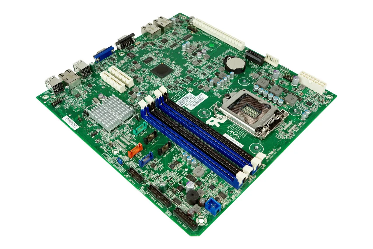
Dealing with BIOS 6 Beeps and 5 Beeps Error Loops: The Advanced Hardware Diagnostic Guide
Introduction
Few computer malfunctions are as frustrating as an infinite boot loop accompanied by a repetitive, sharp motherboard alarm before your display panel can even initialize. When a computer fails to clear the Power-On Self-Test (POST), every pattern of sound signals a specific roadblock encountered by the system firmware. Among these audio sequences, encountering a bios 6 beeps routine or a 5 beeps pattern represents some of the most critical system interruptions possible.
While a 5-beep sequence universally points toward core processing bottlenecks or uninitialized execution units, a 6-beep sequence targets a highly specific, historical, yet vital motherboard component: the legacy keyboard controller chip and its Gate A20 switching line. If your system is throwing these exact error sequences, it means the system cannot safely negotiate instructions with its brain or its fundamental input bus.
This comprehensive satellite guide provides an exhaustive engineering breakdown of why these errors occur, what they mean across different BIOS environments (such as AMI, Award, and Phoenix), and the step-by-step diagnostic procedures required to salvage your system architecture. If you are experiencing general or erratic motherboard sounds that do not match these specific patterns, please refer back to our core system repository: [The Complete Guide for PC Hardware Diagnosis].
The Architecture of Early Boot Routines: Steps 5 and 6
To understand why your system halts and logs these specific alarms, we must look at the linear timeline of the Power-On Self-Test. The system logic does not check storage drives or operating systems until it has established an airtight hardware foundation.
 [Power Button Switched On]
             │
             ▼
 [Step 1: Verify Power Planes]
             │
             ▼
 [Step 2: Initialize System Timer]
             │
             ▼
 [Step 3: Read CMOS Registers]
             │
             ▼
 [Step 4: Check Base System Memory]
             │
             ▼
 [Step 5: CPU Handshake] ──────────► (Failure) ──► 5 Short Beeps (System Halts)
             │
             ▼
 [Step 6: Gate A20 Line Check] ────► (Failure) ──► 6 Short Beeps (Input Lockout)
             │
             ▼
 [Step 7: Initialize Display Adapter]
When the BIOS execution line hits Step 5 or Step 6 and fails to receive a validation signal back from the corresponding hardware register, it immediately halts the startup sequence to protect your components from electrical or logic degradation, forcing the system speaker to sound the alarm.
Core Diagnostic Matrix: 5 Beeps vs. 6 Beeps Decoded
| Audio Sequence Pattern | BIOS Architecture | Engineering Error Meaning | Primary Technical Root Cause |
| 5 Short Beeps | AMI / MSI / ASUS | Processor (CPU) Failure | The execution unit failed to respond, lacks core voltage, or has experienced thermal trip limits. |
| 5 Long Beeps | Gigabyte / Award | Graphic Card Error | The system cannot allocate resources or find a valid video BIOS signature. |
| 6 Short Beeps | AMI / Megatrends | Gate A20 Controller Error | The 8042 keyboard controller chip is dead, loose, or cannot switch into protected memory mode. |
| 6 Long Beeps | Phoenix / Legacy | Keyboard Interface Fault | Physical short circuit inside the data lines of the connected input device or port. |
| Infinite Beeps (Loop) | Universal | Power / Thermal Protection | The motherboard sense circuit detects an immediate low-voltage line drop or missing CPU fan RPMs. |
ℹ️ Technical Note: The Gate A20 line is a fundamental architecture that dates back to the original Intel 286 processor era. It controls how your computer accesses memory above the classic 1MB barrier. Even on modern multi-core AMD or Intel processors running UEFI configurations, the motherboard must emulate or verify this basic 8042 interface sequence during bootup. If a physical hardware short blocks this line, your high-end gaming PC or workstation cannot transition into its advanced protected processing state, locking the system entirely.
⚠️ WARNING: Operating on high-density motherboard circuitry requires strict adherence to electrostatic discharge (ESD) safety protocols. Never remove components, clear physical jumper headers, or unplug internal power cables while your power supply is connected to a live wall outlet. Modern desktop units maintain an active +5VSB (Standby Voltage Rail) that runs continuously through the motherboard traces even when the PC appears turned off. Touching internal components under this electrical load can instantly burn out microprocessors or blow surface-mounted fuses.
Deep-Dive Analysis: The 5 Beeps Hardware Breakout
If your system is locked out by a 5-beep sequence, the motherboard logic is stating that the central processing unit is either physically missing, electrically isolated, or fundamentally broken. Use this advanced diagnostic progression to isolate and fix the fault:
Phase 1: Verifying the EPS 12V Electrical Delivery Plane
A high percentage of 5-beep codes occur during new system assemblies because builders fail to connect the dedicated secondary processor power rails.
-
Locate the CPU Power Header: Look at the top-left corner of your motherboard, immediately adjacent to the physical rear I/O shield panel. You will find a 4-pin, 8-pin, or dual 8-pin socket labeled ATX_12V or EPS_12V.
-
Inspect the Interface: Ensure the modular cable labeled “CPU” (not PCI-E) is inserted firmly until its plastic retention clip clicks over the socket ridge.
-
Trace Splitting: If you are running an overclocked or high-draw multi-core processor and your power supply only provides a single 4-pin connector while the board features an 8-pin socket, the processor may fail to clear the initial low-voltage verification test, triggering the 5-beep alarm. Upgrade your power supply or connect the full 8-pin cluster.
Phase 2: Structural Inspection of Socket Pins and Retainers
If power delivery is verified and the system continues to output 5 beeps, you must inspect the physical interface between the processor silicon and the motherboard socket.
[LGA Socket Pins] ──► Inspect with Magnifier ──► Look for Reflection Irregularities
-
Extract the CPU Assembly: Remove the thermal cooling solution and release the mechanical tension arm of the socket. Lift the CPU vertically out of its slot.
-
Inspect Intel/AMD LGA Sockets: Use a smartphone camera with high magnification or a flashlight to inspect the array of tiny spring pins inside the motherboard socket cavity. Every pin must point in an identical, parallel direction. If you see a spot that reflects light irregularly, a pin is bent or broken, blocking a vital data line to the memory controller or power delivery system.
-
Inspect AMD PGA Processors: If you are operating on an older AMD platform (like AM4), turn the processor upside down and check the gold-plated pins on the CPU itself. Ensure no pins are bent, missing, or coated in stray thermal paste.
-
Decontaminate and Reseat: Clean any dust out of the socket cavity using compressed air. Re-insert the processor, ensuring the golden triangle alignment mark on the corner of the substrate aligns exactly with the arrow mark on the socket frame. Lower the tension arm to lock it down securely.
Deep-Dive Analysis: The 6 Beeps Keyboard Controller Error
When your motherboard returns a 6-beep routine, it means the system firmware cannot establish structural control over the keyboard interface or the memory mapping system. Follow this field routine to isolate the error:
Phase 1: Isolating External Input Short Circuits
Because the legacy 8042 controller chip directly monitors physical hardware ports, a short circuit inside your external keyboard or its connection cable can completely lock up the motherboard’s initialization lines.
-
Disconnect All Input Devices: Unplug every USB device, including your keyboard, mouse, gaming controllers, and USB hubs.
-
Clear Legacy PS/2 Connections: If you are operating a retro or industrial motherboard that features a round purple/green PS/2 port, verify that no old-school keyboard is connected. If a PS/2 connector has bent pins inside its male shell, it will ground out the data and clock lines, causing an immediate 6-beep POST lockout.
-
Perform a Naked Boot Test: Turn the system on with absolutely zero external peripherals connected. If the system clears the 6-beep sequence and successfully displays a “No Boot Device Found” or “Keyboard Error” text on the monitor, your external keyboard or its cable interface is physically short-circuited. Replace the keyboard.
Phase 2: Resolving Static Charge and Logic Locks on the Controller Chip
If the system continues to output 6 beeps with no peripherals attached, the internal logic of the onboard controller chip has frozen. You can clear this state by forcing a deep system power discharge:
[Mains Disconnected] ──► [Hold Case Power 30s] ──► [Bridge Clear CMOS Jumper]
-
Isolate Main Power: Flip the physical rocker switch on the back of your power supply unit to the OFF (O) position and disconnect the AC cord from the wall.
-
Drain System Capacitors: Press and hold down the physical case Power Button for at least 30 to 45 seconds. This forces the high-capacity capacitors on the motherboard’s power distribution lines to dump their stored current into the ground plane, clearing out any trapped logic errors inside the system controller chips.
-
Execute a Manual CMOS Checksum Wipe: Locate the 2-pin or 3-pin configuration header on the motherboard labeled CLR_CMOS or JBAT1. Use a flathead screwdriver or a metal jumper cap to bridge the two pins together continuously for 15 seconds. This wipes the volatile configuration memory and forces the BIOS to completely re-train every onboard device controller from scratch upon the next startup phase.
-
Reassemble and Test: Reconnect your main power line, attach a known-working, simple USB keyboard directly into a primary rear motherboard slot (avoid front case ports or external USB monitors), and turn on the system.
Troubleshooting High-Density Memory and Bus Failures
If both of the above procedures fail to clear your 5 or 6 beep status codes, the issue may be a communication failure on the internal system bus lanes between the processor and your RAM banks.
Step-by-Step Channel Cleaning Protocol:
-
Strip Down to Minimal Post Configuration: Remove all secondary components. Unplug all storage drives (SATA SSDs, mechanical hard drives, M.2 NVMe drives), remove any dedicated sound cards or Wi-Fi cards, and leave only a single module of system RAM installed.
-
Clean Microscopic Contamination: Over years of use, high-velocity cooling fans pull dust, humidity, and micro-particles inside your case, forming an insulative film inside the memory slots and PCIe expansion tracks. Pop out your memory stick, take a clean plastic pencil eraser, and rub it gently along the gold-plated contact pads on both sides of the module. This wipes away any surface oxidation layers without scratching the underlying copper-gold traces.
-
Isolate Individual Slots: Insert your single cleaned RAM stick into the second slot out from the CPU socket (universally designated as Slot 2 / DIMM_A2). If the system still outputs 5 or 6 beeps, swap the stick to Slot 4 / DIMM_B2. If the machine boots up normally in one slot but throws error patterns in another, one of the internal memory bus lines on your motherboard or inside the processor’s integrated memory controller (IMC) is permanently damaged.
[CPU Socket] ──► [Slot 1] ──► [Slot 2: TEST POSITION A] ──► [Slot 3] ──► [Slot 4: TEST POSITION B]
Summary Conclusion
Navigating specialized alarms like the BIOS 5 and 6 beep sequences allows you to skip blind component swapping and target the explicit hardware interface that is halting your machine. Once your processor power planes pass their baseline electrical verification tests and the embedded controller initializes its interface lines successfully, the system will drop its diagnostic lockouts, open the display pipeline, and pass control over to your operating system.
✍️ Author: Bejenaru Alexandru Ionut – [email protected]
🔗 Internal link: https://diagnozabam.ro/sfaturi

Recommendation: Looking for a professional bi-directional diagnostic tool with full system coverage? Use code DIAGNOZABAM for 10% off.
Transparency note: Affiliate link. Purchasing through it costs you nothing extra. View Thinkcar Deal →