
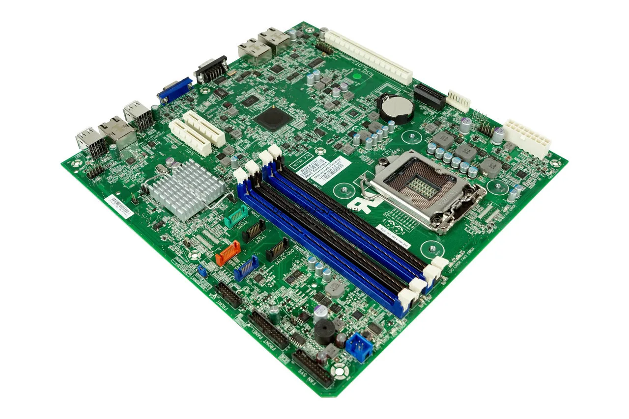
HP BIOS Beep Codes and Blink Codes: Complete Diagnostic Manual
Introduction
Troubleshooting modern Hewlett-Packard (HP) desktop towers, workstations, and laptops requires decoding an integrated audio-visual signaling environment. Unlike legacy systems that rely strictly on internal buzzer speakers, modern HP architectures utilize a combination of audible tones (HP bios beep codes) and visual LED flash sequences (frequently using the Caps Lock or Num Lock keys). This advanced notification protocol distinguishes between simple configuration mismatches and catastrophic board-level voltage failures before the display panel can initialize.
This comprehensive satellite guide maps out the dual-tone blinking matrix found across HP Pavilion, EliteBook, ProDesk, and Omen product lines. If your machine is emitting a continuous, unpatterned tone, make sure to cross-reference our core system document: [The Complete Guide for PC Hardware Diagnosis].
Reading the Dual-Tone Red and White LED Sequence
Modern HP diagnostic codes are grouped into “major” and “minor” categories. When a POST failure occurs, the status LEDs blink in a dual-color pattern:
-
Red Blinks (or Long Low-Pitch Beeps): Represent the major error category (e.g., core component missing or dead).
-
White Blinks (or Short High-Pitch Beeps): Represent the minor error subdivision (e.g., the specific subsection of that component that failed).
[Power On Failure] ──► █ █ █ (3 Red/Long) ──► [Pause] ──► █ █ (2 White/Short) ──► Code 3.2: RAM Error
Because these boards halt power delivery to secondary circuits the millisecond an execution phase drops, understanding the initialization sequence is vital to tracking down failures:
                  [Mains/Battery Power Engaged]
                                │
                                ▼
               [Step 1: Embedded Controller Check] ──► (Fail) ──► 5 Red + 2 White
                                │
                                ▼
               [Step 2: Core Processor Init] ────────► (Fail) ──► 1 Red + 2 White
                                │
                                ▼
               [Step 3: Memory Module Handshake] ────► (Fail) ──► 3 Red + 2 White
                                │
                                ▼
               [Step 4: BIOS Signature Check] ───────► (Fail) ──► 2 Red + 2 White
Technical Diagnostic Matrix: HP Beep & Blink Sequences
| LED / Audio Blueprint (Red + White) | Primary System Error | Detailed Technical Root Cause | Corrective Maintenance Action |
| 1 Red + 2 White | Processor (CPU) Fault | The processor is not detected, lacks main core voltage, or an internal execution unit is dead. | Verify the 8-pin EPS connection on desktops. Requires service center reflow/replacement on laptops. |
| 2 Red + 2 White | BIOS Recovery Loop | The primary BIOS image is corrupted, unreadable, or an update was interrupted. | Trigger HP Emergency BIOS Recovery manually using a key combination. |
| 3 Red + 2 White | Memory (RAM) Error | The memory controller cannot initialize the installed SODIMM/DIMM modules. | Reseat memory modules. Test individual modules in isolation in the primary slot. |
| 3 Red + 3 White | Graphics (GPU) Fault | The integrated chip or discrete PCIe card cannot establish an interface link. | Reseat the dedicated graphics card. Clean PCIe trace pins on desktops. |
| 4 Red + 2 White | Power Plane Failure | A critical onboard power controller or controller chip has experienced an electrical short. | Disconnect all internal storage drives and expansion cards to isolate the power rail. |
| 5 Red + 2 White | System Board Failure | General embedded controller failure or component degradation within the chipset. | Perform an isolated hard hardware power drain. |
ℹ️ Technical Note: On HP commercial desktop lines (like EliteDesk or ProDesk), the power button itself acts as the diagnostic LED indicator. If the power light flashes red three times followed by two quick white flashes, it matches the
3.2memory code exactly. Always check the primary user interface buttons for illumination if your internal buzzer speaker is absent.
⚠️ WARNING: HP laptops utilize highly sensitive component interfaces. Never attempt to add, remove, or swap internal SODIMM RAM modules or wireless cards while the external charging brick is plugged in or while the internal battery management link is attached to the system board. Failing to pull the main battery plug before touching surface-mounted parts can blow the microscopic protection diodes near the memory bus, resulting in a permanent power plane failure (
4.2code).
Deep-Dive Maintenance Procedures for HP Hardware
Phase 1: Initiating an HP Emergency BIOS Core Recovery
If your computer is locked in a 2.2 blink sequence, the firmware signature has failed. You can force the embedded recovery block to overwrite the corrupt flash partition from an uncorrupted onboard backup sector:
-
Isolate Power: Shut down the computer completely and verify all indicator lights are off.
-
Keyboard Override: Press and hold down the Windows Key and the B Key simultaneously while the machine is powered off.
-
Power Trigger: While continuing to hold those keys, press and hold the Power Button for exactly 3 seconds, then release the power button only.
-
Verification: Continue holding the
Windows + Bkeys for an additional 10 seconds. The system will turn on with a black screen, the fans may run at maximum velocity, and an automated BIOS Update/Recovery screen will initialize.
[Hold Win + B] ──► [Press Power for 3 Seconds] ──► [Release Power, Keep Holding Win + B] ──► Recovery Begins
Phase 2: Executing an HP Hard Component Reset (Static Discharge)
Persistent 5.2 chipset errors or logic locks are frequently caused by stray capacitive charges building up within the internal power rails. Clear the electrical field using this sequence:
For HP Laptop Form Factors:
-
Disconnect the external power charger and remove all external USB keys, docks, or display cables.
-
If the laptop features an external removable battery, unclip it. If it is internal, unscrew the bottom shell and disconnect the main battery clip from the motherboard trace.
-
Press down and hold the physical Power Button for a full 15 seconds. This forces the capacitors to dump their stored current through the ground plane.
-
Reconnect the AC charger without connecting the battery first, and attempt to boot.
Dacia ar putea fi repoziționată ca rival pentru Jeep în Europa
For HP Desktop Form Factors:
-
Pull the main power line out of the power supply unit (PSU).
-
Hold the case power button down for 20 seconds.
-
Remove the CR2032 coin cell battery from the center of the board.
-
Bridge the clear CMOS header pins with a metallic screwdriver tip for 10 seconds, reinstall the battery, and attach main power.
Summary Conclusion
By matching the exact red-and-white pulse rhythms of your HP device, you bypass blind hardware diagnostics entirely. Once the core validation phases—such as memory handshakes and BIOS block signatures—clear successfully, the system will hand over control to the primary boot loader.
✍️ Author: Bejenaru Alexandru Ionut – [email protected]
🔗 Internal link: https://diagnozabam.ro/sfaturi
Recommendation: Looking for a professional bi-directional diagnostic tool with full system coverage? Use code DIAGNOZABAM for 10% off.
Transparency note: Affiliate link. Purchasing through it costs you nothing extra. View Thinkcar Deal →