
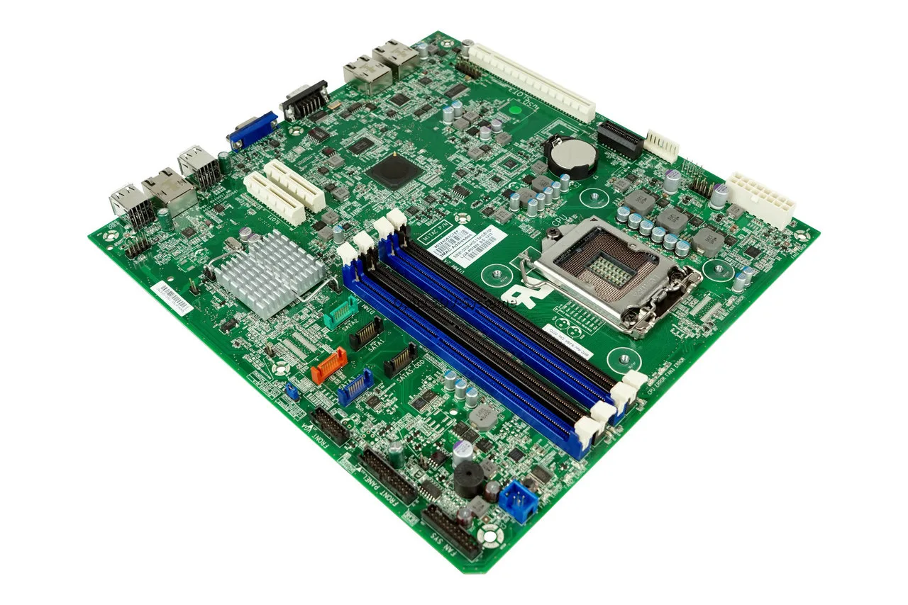
Phoenix BIOS Beep Codes: Ultimate Motherboard Repair & Diagnostics Manual
Introduction
Unlike standard, continuous hardware warning signals, troubleshooting a motherboard running a classic or enterprise-level Phoenix BIOS layout requires a highly methodical approach. Phoenix architectures do not use simple sequences like “three short beeps.” Instead, they utilize a distinct, burst-patterned sequence separated by brief pauses (for example: a 1-2-2-3 or 1-3-1-1 pattern). Missing a single pause during your diagnostic sweep can lead you to swap out a perfectly functional processor when the real culprit is merely a loose system memory module.
This comprehensive satellite guide decodes the intricate system matrix of legacy and modern phoenix bios beep codes alongside industrial ami bios beep core alternatives. If you are tracking down a general hardware alarm that does not use this distinct patterned sequence, make sure to read our foundational anchor document: [The Complete Guide for PC Hardware Diagnosis].
Understanding the Rhythmic Architecture of Phoenix Diagnostics
To read a Phoenix BIOS code accurately, you must count the bursts of sounds between the silent intervals. For example, when a system emits one beep, a pause, three beeps, a pause, one beep, a pause, and a final one beep, this is documented as a 1-3-1-1 error code.
[Power On] ──► █ [Pause] █ █ █ [Pause] █ [Pause] █ ──► Pattern: 1-3-1-1 (RAM Error)
Because these boards halt processing logic the exact millisecond an inspection phase fails, mapping out the boot path sequence is vital to tracking down structural board degradation:
Technical Diagnostic Matrix: Phoenix & AMI BIOS Core Patterns
| Audio Signal Blueprint | Engineering Error Meaning | Micro-Component Point of Failure | Advanced Technical Maintenance Action |
| 1-1-3-1 | Motherboard Timer Failure | System timer chip on the motherboard is unresponsive or desynchronized. | Perform a deep power cycle drain. If persistent, the main chipset clock crystal is dead. |
| 1-1-4-3 | CMOS RAM Checksum Failure | The system configuration data inside the volatile RTC storage chip is corrupted. | Check the onboard battery cell. Clear physical CMOS memory pins to rebuild the checksum layout. |
| 1-2-2-3 | BIOS ROM Code Failure | The physical motherboard flash memory chip cannot pass its data integrity verification. | Re-flash firmware via an isolated USB flash utility slot or manually replace the SPI flash ROM chip. |
| 1-3-1-1 | Base DRAM Refresh Error | The memory controller cannot establish standard internal refresh lines for structural RAM. | Reseat all SODIMM/DIMM modules. Clean contact arrays with electrical contact cleaner or a soft eraser. |
| 1-4-2-1 | Programmable Interrupt Fault | The onboard interrupt controller chips cannot manage incoming system hardware calls. | Disconnect external PCIe cards (sound cards, Wi-Fi modules, NVMe expansion cards) and retest. |
| 2-1-2-3 | Serial / Parallel Port Failure | An integrated motherboard communications controller chip has experienced an electrical short. | Enter BIOS config utilities (if accessible) to disable legacy COM/LPT ports entirely. |
| 3-2-4-1 | Display Matrix Initialization Failure | The primary graphics chip, integrated silicon video subsystem, or PCIe link lane is down. | Ensure clean alignment in the main x16 slot. Swap display adapter to an alternative slot if trace damage is suspected. |
ℹ️ Technical Note: Many workstation, server-grade, and enterprise systems using Phoenix microcode include an onboard diagnostic piezo speaker soldered directly to the printed circuit board (PCB). If your custom computer chassis lacks an internal speaker connection wire hooked up to the
F_PANEL(Front Panel) pins, you will not hear these crucial patterns. Always keep a portable 4-pin motherboard diagnostic buzzer in your toolkit to verify silent POST failures.https://diagnozabam.ro/sfaturi/ro/blog/planetarele-totul-despre-ele/
⚠️ WARNING: Never attempt to pull out memory modules, clean physical board components, or adjust jumper pins while your power supply unit is still plugged into a live wall socket. Modern desktop power distribution systems keep an active +5VSB (Standby Voltage Rail) alive across the motherboard traces even when the computer appears completely powered off. Touching the contacts under this electrical load can instantaneously short-circuit the internal memory bus lanes, rendering your motherboard permanently unrepairable.
Step-by-Step Deep-Dive: Overcoming Memory Refresh & Storage Failures
If your system is locked in an infinite 1-3-1-1 (RAM) or 1-1-4-3 (CMOS) diagnostic loop, follow this exhaustive field service routine to clean your system lines and force a fresh hardware retraining cycle:
Phase 1: Executing an Isolated Hardware Diagnostic Profile
-
Strip Down the Rig: Disconnect every secondary device attached to the board. Remove all storage drives (SATA SSDs, HDDs, M.2 NVMe drives), all graphics adapters, and all USB accessories.
-
Isolate the RAM Banks: Pop out every stick of system memory.
-
Execute the First Power Test: Turn on the power supply. Because a motherboard cannot boot without memory, a healthy board must change its pattern to a raw memory missing alarm. If the beep sequence changes, your motherboard is functioning correctly, and the issue lies within your specific modules or secondary cards.
Phase 2: Restoring Physical Memory Bus Stability
-
Decontaminate the Slots: Over time, airborne dust and moisture form a microscopic insulative film inside the DIMM slots. Use compressed air to blast out the channels.
-
Restore Individual Stick Trace Rails: Take your RAM stick and rub a clean plastic pencil eraser gently along the gold-plated contact fingers on both sides. This wipes away surface oxidation without causing chemical corrosion to the delicate gold layer.
-
Test Individual Channel Lane Logic: Insert only one single stick into the primary slot recommended by the manufacturer (usually labeled Slot 2 / DIMMA2). Turn on the machine. If it boots successfully, repeat the test with the second stick in the same slot to rule out individual component failures.
[CPU Socket] ──► [Slot 1] ──► [Slot 2: TEST FIRST] ──► [Slot 3] ──► [Slot 4]
Phase 3: Forcing a Complete Factory Board Reset
If you are hit with persistent 1-1-4-3 errors, the system configuration table has frozen. You must manually force the board back to its default state:
-
Locate the three physical pin headers on your board marked CLR_CMOS, CLEAR, or PASSWD.
-
Move the plastic jumper block from its default position (Pins 1-2) to the clear configuration setting (Pins 2-3) for exactly 30 seconds.
-
Move the jumper back to its original home before flipping the main power switch back on.
Summary Conclusion
Navigating through patterned burst codes allows you to bypass hours of blind component swapping. Once your system timing lines, CMOS configurations, and base memory circuits can complete an uninterrupted handshake, your system will clear its diagnostic lock and proceed to a normal boot sequence.
✍️ Author: Bejenaru Alexandru Ionut – [email protected]
🔗 Internal link: https://diagnozabam.ro/sfaturi

Recommendation: Looking for a professional bi-directional diagnostic tool with full system coverage? Use code DIAGNOZABAM for 10% off.
Transparency note: Affiliate link. Purchasing through it costs you nothing extra. View Thinkcar Deal →